Perfecting ACE 3000 balancing
More than best main drive balancing
The ACE3000 project is described in
The Ultimate Steam Page by Hugh Odom.
It was a really promising project at its time, but then oil prices declined and decisions in the short term were made.
More to be read on the above page.
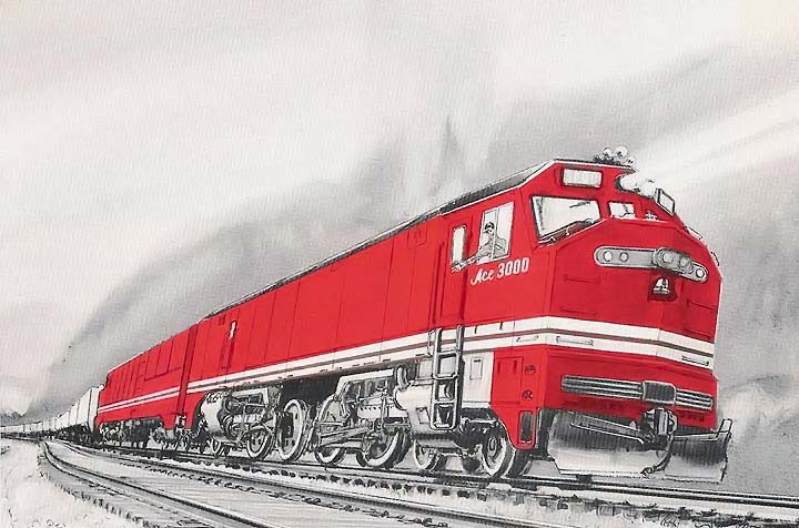
Show preview picture

Image source: https://www.american-rails.com/ace-3000.html
Show design drawings

Image source: http://www.trainweb.org/tusp/ace_det.html
Inside connecting rods are used to tie the two engine units together 180° out from each other.

Image source: http://www.trainweb.org/tusp/ace_det.html
(Click to open in a new tab or window in full size.)
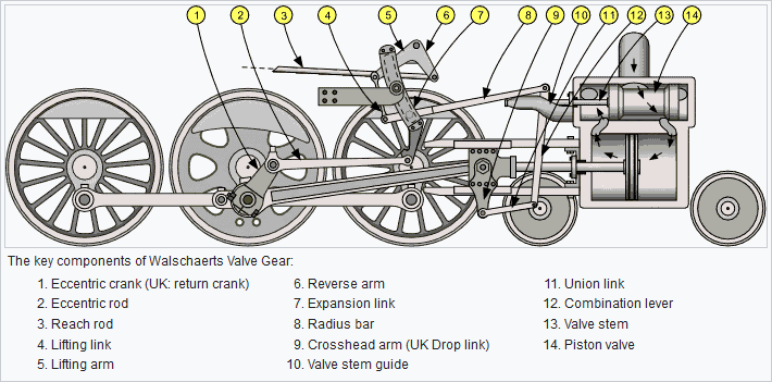
The following text passages refers to the valve gear layout of this drawing.
Please note that the combination lever bearing points of the right valve gear (let's call it front valve gear) are oriented for inside admission and the combination lever bearing points of the left valve gear (let's call it rear valve gear) are oriented for outside admission.
The drive axles are mounted in same orientation referring to the orientation of the cylinders each, but not referring to the whole loco. So all radius bars were moved below the expansion link bearing when driving forward, and vice versa.
Counterweights on drive wheels are mostly used to balance the rotating parts and a bit of the reciprocating parts, depending on the maximum speed of the loco. All of the counterweights that is more than only for the rotating parts effects an alternating vertical force on the drive wheel. If half of the reciprocating parts are balanced by the counterweights, the resulting force ist about constant (in terms of amount) and rotating in opposite direction of the drive wheel. So if a balance shaft is applied with a counterweight that is directed opposite to this force, it can compensate that force, and the engine is, concerning only the resulting forces (but not torque), balanced for its rotating rpm. (But still not for higher frequencies resulting from the limited length of the connecting rod.)
If the above balance shaft is not concentric with the driving wheel (or to be exact about the influence of the main rod gravity center horizontal offset: If it does not have a certain small horizontal distance from driving wheel which but is not practically feasible), the resulting force of the driving wheel and of the balance shaft, along with the distance between them both, results in an additional alternating torque that tends to rotate the engine. This can be prevented by using two balance shafts instead of one, and their correct positioning.
However, on steam locos these balance shafts would have to transmit their forces directly to the drive wheel and not to the main frame as soon as the drive wheel is sprung. This results in a much bigger inert mass of the drive wheel axle, which results in damage of the drive wheel or of the bearings when running on uneven tracks. I had read that only the higher stiffness of Boxpok wheels already led to bearing damages.
So this solution is not suitable. (A much more suitable solution is to be found via the above link "Practicable qualitative balancing" below "Recommended concepts".)
Regarding the potential of the ACE 3000 concept:
At the ACE 3000, the two front drive axles are connected to the two rear drive axles with an angular offset of 180 degrees.
So the reciproating masses of the front piston etc. and of the rear piston etc. can (if having the same weights) compensate each other concerning their inertia forces in longitudinal direction. This not only for rotating frequency, but also above.
So there only the rotating parts (and some part of each main rod) need to be balanced by the counterweights in the drive wheels.
A really superior solution, but there are even more options for balancing:
If e.g. the rear eccentric crank would also be oriented trailing but referred to loco forward direction, then also the front and rear eccentric rods would compensate each other in longitudinal direction (concerning rotating frequency, but not exactly above that).
Perhaps the mass of eccentric rods was too negligible to make different drive axles for front and rear?
Although an horizontal eccentric rod layout would have been enough to just mount the rear drive axle the other way around instead of having different dimensions.
Or was the lower expansion link bearing stress preferred over a (little) better balancing, when driving forward?
If all combination levers and valve pistons etc. were made for same admission type, preferably inside admission, also the front and rear valve piston would compensate each other concerning mass inertia.
I do not see why the rear combination lever and valve piston are made for outside admission, if not because of the higher position of the rear valve piston.
So there seemingly could be an even much more complete mass balancing than only for the main drive, with no extra cost. Not for higher frequencies (than rotating frequency) except for the main drive, but much more than any real steam locomotive has had until now.
This could make this locomotive concept highly competitive also for fast passenger trains.
At least if the last really big disadvantage will be solved - the startup time of the boiler.
The good news is that this already
is solved - for more, see
Mackwell - Boiler.
Need some fresh thoughts and points of view from "out of the box"?
Get in contact and see what is possible!
[Hide]


